Cutting clusters
The ChemShell QM/MM procedures are most commonly used with finite clusters, especially for highly polar materials where cutoffs cannot be used.
Many of the systems to which QM/MM models are applied are condensed phase in nature, and the simulation of such materials is often made tractable by the use of periodic boundary conditions. However, periodic boundary conditions are problematic for QM/MM simulations as many QM codes do not contain the ability to compute the interaction of the QM system with an infinite charge distribution. We have implemented a charge fitting approach which enables a finite cluster to model accurately a single QM defect in an infinite, perfect classical crystalline system. In many cases, this is actually more pertinent to the real system under study than a model system with a periodically repeating defect.
The approach adopted is to start from the perfect, periodic system modelled using the classical force field approach (Figure a), and from it cut a cluster into which the QM model is to be embedded (b). The electrostatic potential in the central active region is computed (using the classical charge model) for both the perfect, infinite system and for the finite cluster (ie (a) and (b)). The difference in these potential datasets represents the error introduced by truncating the cluster.
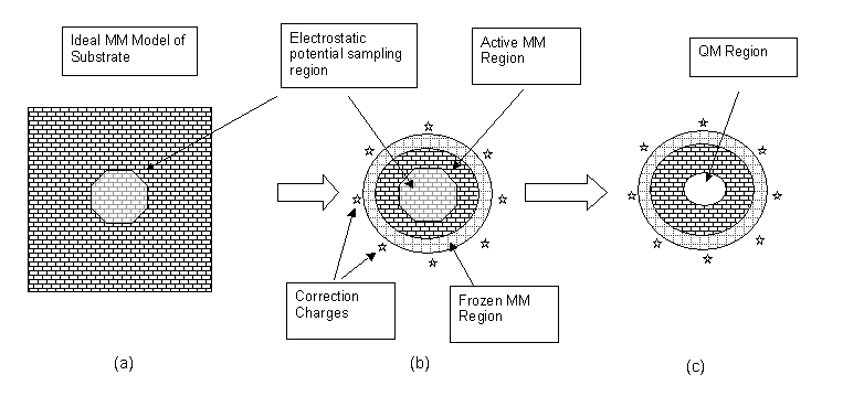
It is often possible to reduce the magnitude of this error by adjusting the charges on the atoms on the surface of the finite cluster. This is particularly true of covalent solids where an adjustment can be applied for each bond cleaved by the cluster generation.
The remaining error in the electrostatic potential can be corrected by defining a set of additional point charges, placed around the outside of the cluster. The magnitudes of these charges are found by least-squares fitting to the error potential so that they compensate for the missing long-range electrostatic terms.
Finally the QM region can be defined (c), and with it a boundary layer if required.
Setting up clusters with construct_cluster
- construct_cluster(...)
The construct_cluster() method is used to generate both spherical clusters
from periodic bulk systems and hemispherical surfaces from periodic slab
systems. The nature of the resulting cluster is determined automatically
by the periodicity of the input crystal.
construct_cluster() can be called as:
my_crystal = Fragment(coords=...)

my_cluster = my_crystal.construct_cluster(...)
where my_crystal is a periodic fragment and my_cluster is the fragment
containing the generated cluster.
The arguments to construct_cluster() are:
- crystal_type
Allowed values:
'ionic': (default) Ionic type of bonding in the crystal'covalent': Covalent type of bonding in the crystal'molecular': Crystal is made of individual molecules. molecules are identified based on the fragment’s connectivity and are either wholly included or excluded from the cluster based on the average distance of the atoms in the molecule from the origin.
- origin
(Default:
[0.0,0.0,0.0]) Coordinates of the cluster origin or atom index (integer) of origin
Note
Py-ChemShell counts atom indexes from 0, so origin=0 will select the first atom as the centre of the cluster
- radius_cluster
(Default:
40.0) Radius (in bohr) of the cut cluster.
- radius_active
(Default:
20.0) Radius (in bohr) of the active MM region in the cluster.
- bq_margin
(Default:
3.5) Distance (in bohr) between the cluster boundary and the outer point charges.
- bq_density
(Default:
5) Density of added outer point charges. The number of added point charges is(4*bq_density**2)+2
- bq_symbol
(Default:
'F') Arbitrary element symbol to assign to BQs for reference in MM codes.
- adjust_charge
Specify a model for adjusting MM charges on the cluster boundary
Allowed values:
'': (default)'coordination_scaled':'valence_model':
- valence_matrix
Charge adjustment matrix for use with the
adjust_charge='valence_model'scheme.
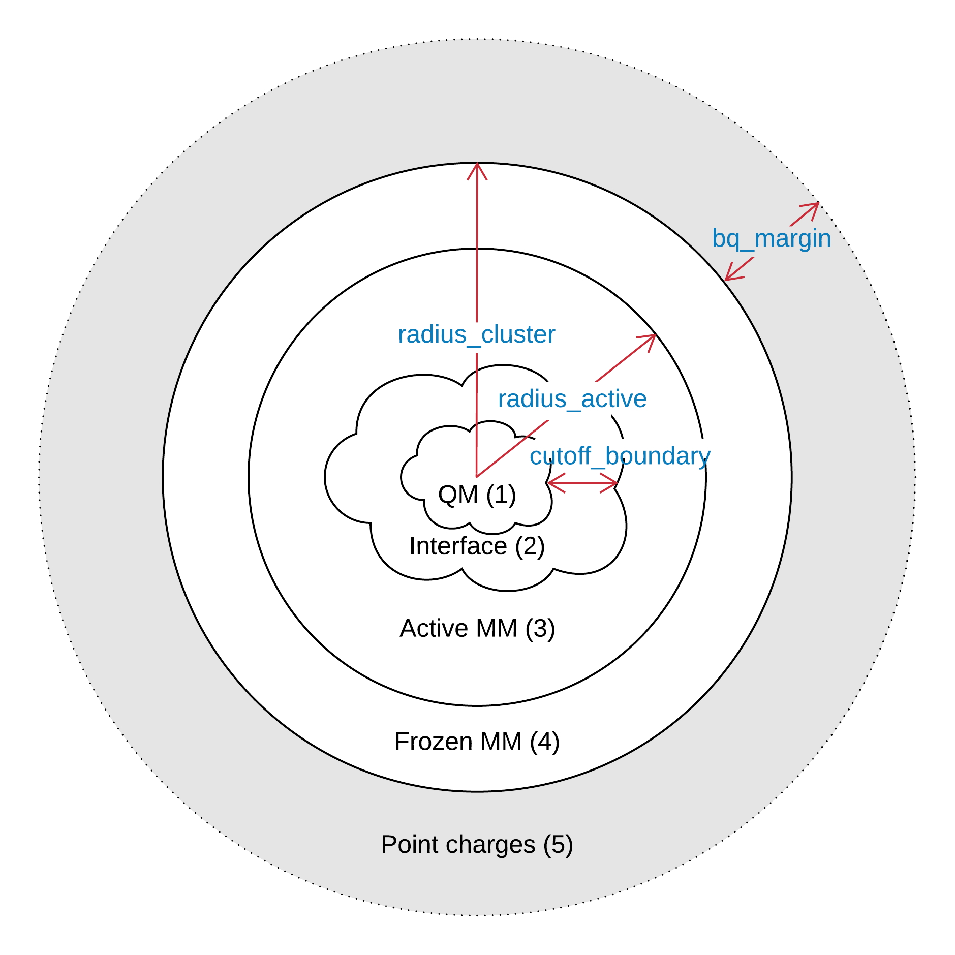
Region 1 - QM; Region 2 - QM/MM interface; Region 3 - Active MM; Region 4 - Inactive MM; Region 5 - Background point charges
Setting up QM/MM based on cut cluster
- partition(...)
construct_cluster() can be called as:
my_cluster = my_crystal.construct_cluster(...)

my_qmmm_cluster = my_cluster.partition(...)
- label_qm
(Default:
'1') Label attached to forcefield type name for the QM region (e.g., “O1”).
- label_interface
(Default:
'2') Label to attach to forcefield type name for the QM/MM interface region (e.g., “O” to “O2”).
- label_active
(Default:
'3') Label to attach to forcefield type name for the active MM region (e.g., “O” to “O3”).
- label_inactive
(Default:
'4') Label to attach to forcefield type name for the active MM region (e.g., “O” to “O4”).
- label_bq
(Default:
'5') Label to attach to forcefield type name for the BQs (e.g., “F” to “F5”).
- bq_symbol
(Default:
'F') Arbitrary element symbol to assign to BQs for reference in MM codes.
- cutoff_boundary
(Default:
10.0) Atoms within this distance (in bohr) from label_qm are assigned to label_interface.
- interface_exclude
(Default:
[]) List of atom symbols to exclude from the interface region
- interface_rigid
(Default:
[]) List of atom symbols to be rendered rigid in the interface region. For use with theqmmm_interface='explicit'only.
- origin
(Default:
[0.0,0.0,0.0]) Coordinates of the cluster origin (output from construct_cluster) or atom index (integer) of origin
- qmmm_interface
There are two definitions for the QM/MM interface region (region label_interface) that can be selected
Allowed values:
'implicit': In the implicit interface, interface atoms are represented in the QM calculation as QM atoms with ECPs attached'explicit': In the explicit interface, the interface atoms are represented as BQs with ECPs attached in the QM calculation and full core-shell MM atoms in the MM calculation (if the shell model is being used)
- radius_active
(Default:
20.0) All atoms within this radius (in bohr) from the origin are assigned to region 3 (active MM).